This paper from Ali Hamdan, Benoît Vinot and Florent Cadoux about a dynamic voltage controller was presented at the CIRED Conference in Roma in June 2023.
Abstract
With the widespread use of Distributed Energy Resources (DER), Distribution System Operators (DSO) are faced with a challenge: the capacity of the grid to host the new sources is not always sufficient. The conventional answers to these challenges have been either to reinforce the grid, which can be costly, or to cancel the connection project altogether. In order to support the development of renewable energy, governments and energy regulators started to enforce an alternative solution: non-firm connections, that involve dynamic curtailment of the generators’ output. Non-firm connections require a controller that may be local or centralised. When using centralised control or “Active network Management” (ANM), the grid operator needs to implement some kind of Distributed Energy Resources Management Systems (DERMS). Most existing DERMS solutions require dedicated hardware and telecommunications, as well as human supervision. While suitable for specific applications with large stakes, such costly solutions may be inadequate for mass deployment, especially at the low-voltage level. We propose an alternative “light DERMS” solution based on the smart metering infrastructure, that aims at massively scaling up LV non-firm connections at a low cost.
Introduction
Non-firm grid connections
In constrained areas of the electricity distribution system, the time and cost needed to reinforce the grid can be a significant deterrent to customers wanting to connect their generators.
To mitigate this, customers may be offered a dynamic type of connection that limits the times in which the generator can export power and/or the maximum power that can be exported. Such dynamic connections are referred to as “non-firm”, and temporarily limiting the export of generators is commonly referred to as “curtailment”.
Power curtailment induces a loss-of-gain for the producer; in return, grid reinforcement is avoided, as well as the costs and delays associated with it. In certain situations, this trade-off may be advantageous for the power producer. In effect, non-firm connections thus make it possible to connect more producers to the existing grid without having to reinforce it.
In some countries, such as France [[1]], non-firm grid connections are enforced by law. In practice however, they are currently used only selectively, for the connection of some specific large generators to the Medium Voltage (MV) grid. Non-firm connections are however not yet deployed massively, notably not at the Low Voltage (LV) level. This is the topic we will investigate in this paper.
Local versus centralised implementation of the voltage controller
From the contractual viewpoint, a non-firm connection is simply a specific bilateral contract between the DSO and the producer.
From the practical viewpoint, implementing non-firm connections requires automated management of the grid: the grid must be observed, and the flexible generators controlled dynamically, so as to prevent the constrained part of the grid from violating voltage and/or current limits.
The control may be implemented in a centralised or decentralised manner. A centralised management scheme, often referred to as “Active Network Management” or ANM, strives to continually monitor an entire area of the network via various sensors and to dynamically share its capacity among any number of controllable generators, so as to avoid exceeding the defined network limits. A decentralised scheme usually simply reduces the power injection based on local voltage measurements (P(U) control), sometimes after acting first on reactive power (Q(U) control).
Both types have their own advantages and drawbacks. They may be used simultaneously within the same grid in an attempt to get the best of both worlds. In this paper, we discuss centralised control.
Choice of the supporting infrastructure
Active Network Management schemes require the use of sensors, telecommunication equipment and centralised decision-making units to monitor and control the grid. This raises the question of whether dedicated hardware should be deployed specifically for the purpose of implementing non-firm connections, or some existing assets may be leveraged for that purpose.
As far as LV grids are concerned, and keeping in mind our objective of minimising the costs for implementing an ANM scheme, we argue that the existing smart metering infrastructure (AMI or “Advanced Metering Infrastructure”) offers all the necessary features, and should be reused.
Experimental smart grid platform
Motivation
Non-firm connections introduce the entirely new notion of real-time monitoring and control at the LV level. As any disruptive change, they require several levels of thorough testing and validation before actual deployment.
While lower levels of testing, such as unit testing, can be performed on individual components or small subsystems (e.g. to test the interoperability of two components), higher levels of testing require a working prototype of the full system. In the context of AMI-based non-firm LV grid connections, “a working prototype” means an LV grid that includes smart meters and at least one generator.
It should also be possible to modify the inner working of the AMI, and to curtail power generation as much as we need for testing purposes. Finally, we need third parties (if any) to be tolerant to any malfunctions, such as overloads, overvoltages and power cuts, while the system is being developed and is not yet fully functional.
These last three requirements are not met on the real grid; in particular, DSOs are usually very reluctant to provide access to the real-world AMI for R&D purposes, and are not willing to take the risk that current or voltage constraints may occur in the grid. In order to carry out research and development work in the area of non-firm grid connections, it is thus mandatory to build a laboratory setup that replicates the physics of a real-world grid, in a separate and controlled environment.
Technical requirements
In the context of non-firm LV grid connection, and considering that G3-PLC has limited capabilities compared to other modern communication technologies, we considered that the AMI was a crucial part of the system and had to be reproduced with accuracy:
-
Firstly, in order to be able to do unit testing of the integration of the controller with the data concentrator and smart meters;
-
Secondly, in order to check that the extra burden due to the ANM, in terms of telecommunication (load on the PLC channel) and concentrator resources (memory, CPU usage), could be handled by the AMI.
-
Thirdly, in order to assess whether the controller is robust enough with respect to telecommunication disturbances and failures.

For these reasons, when designing and building our setup, we strived to use the very same technologies (e.g. off-the-shelf G3-PLC smart meters) as those that are used in the real grid, in France. We also designed the setup in such a way that the quality of PLC communication could be controlled: the impedance of lines is adjustable in the range of G3-PLC communication (namely a few tens of kHz). In this way, the disturbances of telecommunication that are commonly observed in the real world can be reproduced in the laboratory setup.
Presentation of the experimental platform

The platform represents a 3-phase LV grid with the following units:
A substation unit: equipped with a Power Line Communication gateway (G3-PLC) that acts as the data concentrator.
House units: each unit is equipped with a controllable active power consumption module, a controllable PV generation module, a smart meter, local monitoring devices and a local computing unit on which a local controller can run. The smart meter has a one-way external communication port that is used to pass the curtailment setpoints to the inverter. In effect, the smart meter thus acts as a gateway that receives data from the concentrator via PLC communication, and transmits it to the inverter using wired communication.
LV cables: modelled with the equivalent impedance of their lumped models. The cables are made configurable so that different grid topologies required by different case studies can be tested. The impedance at 50 Hz is fixed and made 100 times larger than the actual impedance of the line we are emulating; conversely, all powers (hence all currents) are scaled down by a factor 100, so that the voltage drops and rises are correct and accurately measured by smart meters, while reducing the overall size and cost of the setup. In addition, as explained above, the impedance in the range of a few tens of kHz (G3 PLC range) is adjustable, in order to produce different telecommunication situations ranging from almost ideal communication to the complete loss of PLC communication.
With all the houses equipped with a controllable Distributed Generation (DG) unit and a smart meter and with the topology being configurable, the platform can be used for a variety of study cases of non-firm LV connections.
Control design
The two levels of control
The controller is composed of different software modules that compose a two-layer control system:
-
a “main module” runs centrally inside the data concentrator,
-
and “distributed modules” run at the level of an “energy box” on the customer’s premises.
The local energy box is responsible for applying the setpoints received from the central controller, and to apply some predefined local strategy whenever these setpoints are not received in due time. The control logic is thus purely centralised when communication is satisfactory, but may become decentralised when communication is degraded.
Note that the decentralised control mentioned here, which is a temporary backup mode of a centralised ANM scheme, is different from the purely decentralised controllers such as P(U) and Q(U) controllers that we mentioned in the introduction. For instance, when communication is lost and regardless of any local voltage measurement, our backup local controller may reduce the power output of generator to 70% of its power output because it has been calculated beforehand, and programmed into the local controller, that this 70% threshold was sufficient to avoid the targeted constraint, such as overloading the distribution transformer.
Control objectives
The choice of the control logic and the value of its internal parameters (margins, gains….) was driven by the following objectives.
-
Optimise the trade-off between energy curtailment and grid constraints: a more conservative controller may be able to avoid most if not all grid constraints, at the expense of higher energy curtailment; while a more permissive controller may opt for a lower level of curtailment (hence inducing lower loss-of-gain for the producer), but may also lead to occasional overvoltages or overloads.
-
Optimise the trade-off between, on the one hand, controller performance in the sense of the above item (low constraint violations and low energy curtailment); and on the other hand, consumption of telecommunication resources. A given controller may exhibit high performance, that is to say, it may curtail almost exactly just the minimal amount of energy that is required to perfectly avoid any grid constraint; but it may also be very demanding in terms of telecommunications. Conversely, another controller might have lower performance but also be much more economical in terms of telecommunication resources.
-
Optimise the trade-off between robustness to communication disturbances, and energy curtailment: when communication is detected to be lost with the central controller, a more conservative distributed controller may quickly increase the curtailment just to be on the safe side (“not knowing how much to curtail, because communication is lost, I should curtail the maximum amount for safety reasons”). A more permissive distributed controller may try to infer the appropriate level of curtailment, without systematically resorting to curtailing the maximum amount.
-
Optimise the amount of curtailed energy while enforcing some agreed upon “fairness rule” among the participant producers: simply aiming at minimising the energy loss will typically lead to systematically curtailing producers that are far away from the substation, because these are the generators that have the strongest effect on grid voltage per curtailed kW, while sparing the generators that are located closer to the distribution substation. This behaviour might not be acceptable for the producers, so that a trade-off between fairness and efficiency (in terms of curtailed energy) has to be found.
-
Optimise the complexity of the controller: a controller that requires knowledge of the topology of the grid, the impedance of the lines, etc, might be able to yield better performance than a simpler generic controller based, for instance, on PID or self-learning. On the other hand, a complex controller based on a grid model will require more complex input data, and will be tied directly to a certain network topology; as a consequence, it might not be usable with other networks, or malfunction when the topology of the network is changed without simultaneously updating the grid data embedded into the controller. Also, an overly complex controller may add a substantial and possibly prohibitive burden to the data concentrator in terms of memory usage and computation resources.
Implementation and Experimental Results
Control logic
The controller that we proposed is inspired by the standard PID logic, with two main adaptations: firstly, it is modified to adapt the unilateral nature of the voltage constraint; and second, it slightly deviates from the pure feedback control logic in the sense that it makes use of past active power measurements, not only voltages.
We define the following Proportional-Integral (PI) corrector μ(t) where the non-firm power limit is defined by α(t) = μ(t)pmax:
μ(t) = 1 – σϵ(t) – 𝜏λ(t)
Where:
𝜎 and 𝜏 are the two corrector gains
ϵ(t) is the voltage violation of the most violated constraint: max( u(t) – umax ) ∀t
λ(t) is the term that measures the non-negative integration of the error over time
In discrete time, the feedback mechanism then writes:
𝜆𝑡 = max(( 𝜆𝑡−1 + ϵ𝑡−1), 0)
𝜇𝑡 = max( min( 1−σ, ϵ𝑡−1 − 𝜏𝜆𝑡, 1), 0)
If ϵ𝑡−1 > 0 :
𝜆𝑡 = (1/𝜏).(1 – σϵ𝑡−1 – 𝜇𝑡)
𝜇𝑡 = min( 𝜇𝑡, (p𝑡−1/ pmax))
The last term where ϵ > 0 is the correction factor that limits voltage overshoots using the history of active power measurements, which as noted above, deviates from a pure feedback control logic.
With respect to our above-mentioned control objectives, note that the proposed controller favours fairness, in the sense that all producers are receiving the same power quota, over technical efficiency (i.e. minimising the total amount of energy curtailed). Also note that the proposed controller favours simplicity, in the sense that it does not assume any knowledge of the details of the underlying electrical system (topology, lines characteristics, etc). It is thus particularly simple and easy to implement, does not require elaborate input data, and induces a negligible overhead in terms of memory usage and computation resources in the data concentrator.
Experimental Results
The control proposed in the previous section was implemented and deployed on our experimental platform. We replicated a 3-phase LV grid with seven individual houses, as depicted in Figure 2.
Figure 3 shows a congestion scenario using the network of Figure 2 where all DG units are flexible. The voltage limit is set to 248 Volts which is about 8% above 230V, the nominal voltage in France. The control time steps were set to 15 minutes. Figure 3 shows the different voltage levels in the network without and with control respectively.
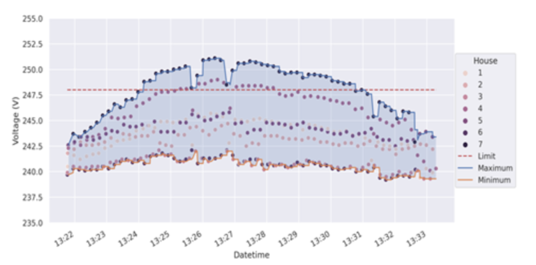
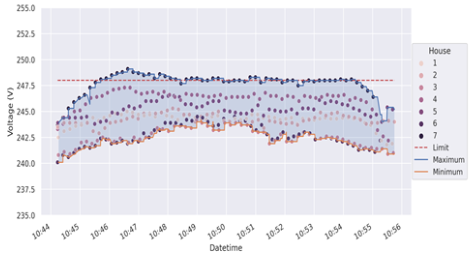
The results show that the controller was able to maintain an acceptable voltage in the network where otherwise the voltage of the houses farther from the substation suffer from over-voltages during the period of peak production. It also shows that occasional violations still occur when the controller is used, especially in the period immediately after voltage has reached the limit. These violations are a direct consequence of the fact that the control relies on a basic PID-style controller and on slow communication. Violations may be reduced by adding some security margin to the controller, or by switching to a more elaborate controller logic, or by decreasing the duration of control time steps. But, as noted in the “Control Objectives” section, all these options have drawbacks as well, and the final design of the controller will inevitably consist in a compromise between conflicting objectives.
Conclusion and perspectives
This paper presents a practical and cost-effective “light DERMS” solution for implementing non-firm connections in the low voltage grid. The approach relies on the existing advanced metering infrastructure, eliminating the need for specific hardware. We presented an experimental platform for testing and validating the proposed solution. When designing and building the platform, special attention was given to replicating the real-world AMI with great accuracy. We also presented a basic controller inspired by the standard PID control logic that we adapted to the active network management of non-firm LV generators. Finally, we implemented the proposed controller on our experimental platform and provided some experimental results that demonstrate the practicality of our approach.
Our objective is now to deploy our controller on the real-world distribution grid. A first ongoing step is an experiment that we are currently carrying out on a scale-1 grid as part of the European Research Infrastructure supporting Smart Grid and Smart Energy Systems Research, Technology Development, Validation and Roll Out (ERIGrid 2.0) at the SysTec Test Center for Smart Grids and E-mobility [4]. We will then proceed to a field test with a DSO partner.

Références
[[1]] Arrêté du 12 juillet 2021 d’application de l’article D. 342-23 du code de l’énergie. Schéma régional de raccordement au réseau des énergies renouvelables et établissement de la quote-part (Articles D342-22 à D342-24)
[[2]] Directive (EU) 2019/944 of the European Parliament and of the Council of 5 June 2019 on common rules for the internal market for electricity and amending Directive 2012/27/EU
[[3]] Muller, L., and Cadoux, F., 2023. “Non-Firm Grid Connections For Low-Voltage Generators: A Case Study”, Proceedings CIRED conference, AIM.
[[4]] Schäfer, N., Gunter A., and Thomas D., 2021, “Fraunhofer IEE – SysTec Testzentrum für intelligente Netze und E-Mobilität”